a
Please refer to our new Engine Bearings page at:
http://store.440source.com/Bearings/departments/18/
For bearing info, see below:
|
a Please refer to our new Engine Bearings page at: http://store.440source.com/Bearings/departments/18/
For bearing info, see below: |
|
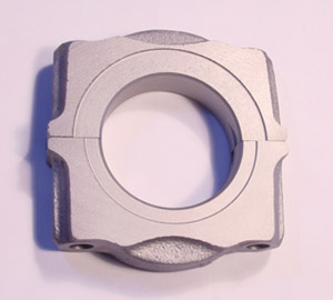
Main Bearing Info. Because "B" (361/383/400) and "RB" (413/426/440) engines use different size main journals, each will have a different size main bearing. The "RB" uses a 2.750" main journal diameter, while the "B" uses a 2.625" so the two sizes are specific to each engine, however there is one additional difference... From the beginning of production (when these engines were designed) in 1958 up until the 1973 model year the diameter of the thrust surface's outer edge (on the #3 bearing) will be approximately 3.470" for the "B" engine and 3.600" for the "RB" engine. Starting in the 1974 model year, this diameter was increased approximately .280 thousandths to 3.750" for the "B" engine and 3.880" for the "RB" in order the give the thrust surface more surface area. To allow the new larger bearings to fit, the machined recess area in the block webbing and the main cap in which the thrust bearing shells fit was increased an equal amount. In the picture below, we have put two #3 thrust bearing main caps together. The one on the bottom is from an early block, and the one on top is from a late block. You can see the difference in the size of the machined recess area.
We refer to the pre '74 bearings as "Early" and the 1974 and later as "Late." It is possible to use the early (smaller) #3 bearing in all blocks, regardless of the year manufactured. For this reason, we offer bearings with the "Early" style thrust flange only. Using the later style bearings in an early block is not possible since they will be too big to fit in the smaller machined recess area. All other bearings except the thrust (# 1, 2, 4 & 5) are the same for all years. This Chrysler TSB (Technical Service Bulletin) from January 21st, 1974 explains the changeover in detail:
|
|
Following is a detailed article in which we attempt to clarify the difference in construction, materials, fit, etc, between Clevite's different bearing series (types,) as well as a general guide to engine assembly as it relates to bearing fitment. Every engine builder and/or machine shop has their own preferences for how they like to set things up, and what series of bearings they like to use (etc, etc,) so be sure to collaborate with them before ordering. Opened bearings are non-returnable. This is for educational purposes only, it is not meant to be a substitute for an experienced, professional engine builder and/or shop. Just as you would not attempt to perform surgery after reading a pamphlet in a doctors office, you should not attempt to assemble a performance/racing engine without the proper experience / knowledge / tools, etc. First, we will cover the differences in the construction of the various "series" of bearings Clevite offers. P Series: Clevite's P series are the original staple bearing. Recommended for stock rebuilds up to some performance use, these tri metal bearings are made from TM-77 material. They start with a hardened steel back for strength and support. Over that is a cast copper lead lining to provide the durability and support to withstand the loads of engine operation. Then a nickel plating is applied to prevent interaction between the copper lead and the final layer, a strong, extra thin (.001" or less) electroplated overlay of babbitt. Babbitt is a tin or lead based alloy with varying amounts of antimony, copper or arsenic which is designed to resist flaking and is very soft by nature. This helps to give the bearing embedability (the ability for stray particles to be "absorbed" by the bearing so they don't rip the crank journal to shreds), conformability (the ability of the bearing to "conform" or adapt to any out of spec surfaces or distortion) and resistance to both seizure and corrosion while still withstanding the high loads a performance engine can generate. Finally they are flash plated with a lead/tin mixture to help protect them and mostly make them look better, (yes this step is mostly cosmetic.) These bearings have high crush for better retention and their high eccentricity helps to accommodate any housing bore distortion. P series are not clearanced for aftermarket cranks with larger crankshaft fillets, although they will usually still work correctly, and any competent shop should be able to easily perform this operation to them if needed. For the low deck ("B") engine main bearings, the "P" series is the only bearing offered by Clevite. We've used them in many high performance builds and found them to work great. We offer them pre-champhered for this application for an extra charge. H Series: This is Clevite's standard performance bearing. Originally developed for Nascar racing, H series are made of the same TM-77 material as the P series, and include most of the features described above, however they are not flash plated with the lead/tin apparently in an effort to help them seat better. They also have enlarged champhers to help them clear bigger crankshaft fillets. In rod bearings, these are available in .001" oversize, standard (.000") and .001" undersize, making them an ideal choice for those who want more flexibility in setting their clearances. They also have a medium level of eccentricity. When available, this is the bearing we offer in all of our stroker kits. M Series: "M" stands for Micro Babbitt, and these bearings are made of Clevite's B-2 material. This consists of a hardened steel backing, to which a .006" thick layer of babitt material is bonded. Because babbitt is very soft, these bearings have an outstanding level of conformability, (the ability of the bearing to "conform" or adapt to any out of spec surfaces or distortion) for applications where the crankshaft may be subjected to severe deflection under load. However, the downside of this is that the life of these bearings can be very short, and these are generally considered a "race only" item. Although some engine builders are familiar with and prefer this style of bearing, it is generally accepted that the H series will do just as good a job without the short lifespan, making the M series in our opinion, not the best choice for all but the most specialized of applications. V Series: The "V" series were originally manufactured by the Vandervell company in England, Clevite bought Vandervell and is now distributing their bearings under the Clevite name as the "V" series. While the V series lead indium material does work great as a performance bearing, we've found physical fitment issues with how the V series rod bearings fit into most aftermarket "H-beam" style rods (detailed below,) and due to availability issues, we generally just go with the H series instead.
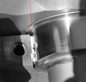
Bearing Fitment and Assembly: During assembly, proper bearing fitment and clearances (which we explain below) should be checked by a skilled engine builder. Back in the days when almost everybody used only stock factory components, checking for the correct bearing "clearance" was usually the only step required. The main reason for this was that in days past, aftermarket parts such as 4340 steel cranks and H beam style rods were very, very rare and expensive (especially for Chryslers!) In the rare case someone would spend many thousands of dollars for these parts, they would usually have enough sense to protect their investment by bringing the parts to a knowledgeable engine builder for proper assembly. Most professional engine builders do their job full time as a career and spend many many years learning the various nuances and acquiring the extensive tools and equipment necessary to build high performance engines. They understand what is involved in fitting together the many different parts available from several different manufacturers, and often they will have preferences as to which type or style of parts they will like to use, and/or have experience with. Nowhere in the engine is this more true than the bearings. Now that the cost of aftermarket parts has come down considerably, many people are buying these previously high dollar parts themselves and attempting assembly in their garage. There is absolutely nothing wrong with this! However, just because the parts have come down in cost does not mean building or assembling a high performance engine has become simpler, easier or less detail oriented. One of the most important areas during the assembly process will be in taking the time to make sure the bearings fit and function properly. It is one of the most critical steps you can take to ensure the reliability of the engine. Below we will attempt to explain how to do this and what to look for. We have separated this article into two parts, Main bearings and Rod bearings. None of it is rocket science (as some shops would have you believe,) it's just a matter of paying attention to details and knowing what to look for. Rod Bearings: We have tested the different types and series of rod bearings in the majority of brand name aftermarket rods available. We have found a very large difference in the specifications (measurements) between aftermarket connecting rod suppliers. This is not a manufacturing issue (most rods are consistent from set to set,) but rather a situation resulting from the fact that their are several different companies making aftermarket rods, and each manufacturer has developed the technical drawings for their rods independently of each other. Specifications such as the distance between the bearing tangs in the cap and beam of the rod, the overall width of the big end of the rod, the size of the chamfer cut, and the width and positioning of the tangs themselves in the rod (this is the measurement from the end of the tang out to the edge of the rod) will all affect how a specific series of bearing fits in a specific rod, and how the bearing is therefore located on the crankshaft journal. Some manufacturers' rods (for example) will fit the V series perfectly, while the H series will require slight modifications to fit properly. Rods from a different manufacturer (such as most of our rods) will fit the H series better, while the V series may need slight modifications. It doesn't seem to make sense that two different bearings (both from the same manufacturer,) listed to fit an identical application would vary in the way they fit, but that is the case. When test fitting the bearings in the rods, and then onto the crank, there are four different areas you should pay attention to. #1) Bearing "Clearance" Traditionally, bearing "clearance" (the amount of "space" between the crank journal and the bearing itself) is the most commonly checked specification. For a bearing to function correctly, it must be able to ride on a cushion of oil (commonly known as a "wedge.") In order for the wedge to function correctly, the bearing clearance should be within the ranges listed in the bearing tables (supplied by Clevite) for the bearing model and/or series you are using. There are two ways to check this. The first is to put "plasigage" (a small piece of wax-like wire) on the crank journal and torque down the bearing on the crank. The wax will compress to a certain thickness, which will tell you the clearance. Be careful not to rotate the bearing while doing this or it will smear the wax and give a false reading. The second (and usually more accurate) way is to measure the diameter of the journal with a micrometer, and then torque the bearing in the rod or main cap (without the crank.) Then, measure the diameter of the bearing. Subtract the diameter of the journal from the diameter of the bearing and you will have the bearing clearance. This method also allows you to check the eccentricity (or egg-shape) of the bearing by measuring at different points such as 12 and 6 o'clock verses 9 and 3 o'clock. #2) Alignment of the upper and lower bearing shells. Because of the situation with aftermarket connecting rods we explained above, (where the bearing locating tangs may very slightly between manufacturers,) depending on the combination of rod and series of bearing you are using, the bearing shells may not line up exactly, or be "offset" slightly. This is most common in the "V" series rod bearings when used in our rods. It generally does not cause a problem, however you must be sure the amount of which the bearing is offset does not cause a issue with the outer edges of the bearing. When referring to fitment of the "outer edges" this can be broken down in further detail to the "outside facing edge" which is the edge which will fit near the radius at edge of the crank, and the "inside facing edge," which will face the opposite rod in center of the crank journal. Next, we explain what to look for in both these areas. #3) The "outside facing" or "Chamfered" or "Narrowed" edge of the bearing. This is the edge that butts up against outer edge of the journal or the "radius" of the crank. This is where many people will tend to have fit or interference issues with aftermarket cranks, so please read this section carefully. When Chrysler originally made crankshafts for our awesome muscle cars, unfortunately their number one priority was cost. To keep costs down, virtually all factory cranks were "undercut." This means when they were first finish machining the crank from a raw forging, they would "plunge cut" (cut straight down into) the edges of the journal, and then come in with a flat grinding wheel and finish the journal surface flat. This is more economical because it allowed them to continue to dress the grinding stone all the way down until they had used it up completely, allowing more cranks to be ground from any given grinding wheel, and thus keeping the bean counters happy. If you look at edges of a factory crank you can still see small grooves in the corners left over from the plunge cutters. The only problem with this approach is that it puts a very sharp angle (or corner) at the edge of the journal. When the engine is running under power, The force from the exploding fuel is transferred through the piston, down the connecting rod, and as this energy gets transferred into the rotational axis of the crank, much of the stress gets absorbed and focused on this sharp corner, making it a weak spot. Newer aftermarket cranks (such as ours) are made with a much wider radius (or gradual turn) from the flat (horizontal) part of the journal to the (vertical) side of the journal. This is a much better design. Because the turn is gradual, it allows all this stress to be evenly spread out (and dissipated) along this gradual curve, rather than focused in the sharp corner like a factory crank. However grinding cranks in this fashion requires the grinding wheel to be constantly re-dressed with the radius, giving the wheel a much shorter life. The other complication that a radiused crank can cause is that because the radius is physically larger, it will occupy some of the same space that used to be used by the bearing. Because two objects (obviously) cannot occupy the same space, the bearing must be modified so that the outside edge does not "hit" the radius of the crank. This is the "oversize fillet clearance" we talk about in the bearing table above. Clevite's "performance" series of bearings (H,V, and M) will come with either a "champher" (45 degree cut or bevel) on the outer edge, or they will be of a "narrowed" design where the entire outside edge of the bearing is narrowed (the overall width of the bearing is made not as wide) to avoid hitting the crank radius. Clevite's "P" series, (stock replacement style) will not come with this extra radius clearance, and if you use these bearings on an aftermarket crank, you will need to machine the bearing yourself for this purpose. This is a fairly easy operation which usually involves clamping the bearing in an old rod and using a large drill press or milling machine to cut the needed champher in the outside of the bearing. However, as we specify above, the position of the bearing locating tangs can and will vary between manufacturers, (and even in factory parts.) This can, (in effect) "shift" the bearing closer to the radius, causing interference issues. Also, the size of the radius on the crank can vary from one manufacturer to another, so the clearance between the radius and edge of the bearing should always be checked, even if you are using pre-chamfered or narrowed bearings. The pre-chamfered or narrowed bearings will usually be sufficient in most situations without modification, but occasionally there may still be a small amount of contact. This contact will be easy to see in the mockup phase of assembly because it will usually make a small shiny line on the edge of the bearing where the contact is being made. Also, the bearing will not allow the rod to slide all the way to the edge of the crank journal, and will affect side clearance measurements. One effective way to make sure your bearings are not contacting the radius is to put some machinists' blue dye (known as Dykem) on the edge of the bearing, and rotate the assembly. If the crank's radius wipes off the blue dye on or near the edge of the bearing, it will show you exactly where the contact is, and exactly where to remove material. If you find you do need to remove any material from the edge of the bearing, you can take a tool called a bearing knife or "bearing scraper" and scrape a small amount of material off the edge of the bearing until you have enough clearance. These tools are listed on our "Tools and Supplies" page. In extreme cases such as trying to put a completely un-chamfered bearings on a radiused crank, the bearing will simply "lockup" as you try to tighten it and it binds onto the radius. Clevite will "legally" recommend that you should never modify their bearings, but this is not a real world solution to the unique issues faced when building a high performance engine. If bearing modification was never required there would not be a tool called a "bearing knife" designed to scrape material off of the edge of a bearing. #4) The "inside facing" edge. This is the edge opposite the chamfer, in the center of the journal, between where the two rods would come together. The main thing to check for here is that the edge of the bearing does not protrude out farther than the edge of the rod. Torque the bearing in the rod and lay it on a straightedge. As long as the bearing is equal to or narrower than the rod itself, there should be no problems. The only bearings we have ever found to have an issue with this is the "V" series rod bearings, CB1512V. If the bearing does stick out a little, take some material off the edge until it is inside the rod. If the bearings were to stick out farther than the rod, they would grind into each other during operation, causing a level 5 bad day. Some engine builders even like to take the bearing down further (a few extra thousanths,) increasing the clearance and assuring plenty of oil can drain out of the bearing, helping to keep the bearing cool and the oil circulating quickly. The downside to doing this is that is reduces the surface area of the bearing. The more surface area a bearing has, the more it can distribute (and dissipate) the load it carries over that area, making the bearing stronger and more capable of handling all those ponies. Main Bearings: We have tested nearly every series, type, and configuration of main bearings Clevite makes as well. Similar to the description above with connecting rods, when a bearing fits into its housing bore, it's exact location will be determined by small "locating tangs" machined into the block. There is a tab or notch in the bearing which fits into this locating tang and determines it's position. Chrysler never intended their blocks to be used in the way we are using them today, and they were not incredibly accurate when they were machining their blocks. Therefore, the exact positioning of the main bearing locating tangs (and by extension the main bearings themselves) cannot be guaranteed, and will depend on how accurately Chrysler machined the specific block you are using. We have measured over .060" difference in bearing tang locations from block to block. Our research has found that for SOME applications, using a non chamfered main bearing will not be a problem. Depending on the factors listed above in the specific parts you are fitting together, you may find that even the non chamfered main bearings will not contact the radius on the crank. Using the method of checking described above with blue machinists dye is highly recommended. Here is a picture of an engine with one of our Platinum Series stroker cranks, and non chamfered MS877P main bearings. Notice the area the arrow is pointing to, and how there is plenty of space between the bearing and the radius on the crank.
If the locating tang in this particular block had moved the bearing farther over toward the radius, the outer corner of the bearing would have to be relieved with a bearing knife, similar to how we describe above in the rod bearing section. For extra insurance, (and a better bearing material and construction) you may want to upgrade to a chamfered H or V series performance main bearing, but we have found the "P" series main bearings (as pictured above) WILL work for most applications. However, YOU MUST ALWAYS CHECK THIS DURING MOCKUP! For certain applications, such as low deck 383/400 engines, non-chamfered "P" series main bearings are the only bearings Clevite offers, so you may have no choice but to chamfer them yourself (or have your shop do it for you) if you find it is needed during assembly. As we said earlier, none of this is rocket science. In a nutshell, it's just a matter of common sense and taking the care and time to make sure the bearings and crank are fitting properly, (as in not contacting each other.) Happy engine building and hopefully we'll see you at the racetrack! |
(775) 883-2590